
Creating a Smart Home with Blynk
All of the connected downstream components are controlled by the GreenPAK device, a configurable mixed-signal IC (CMIC). Blynk is a platform compatible with both iOS and Android smartphones. It can interact with various microcontrollers (e.g. Arduino, NodeMCU, Raspberry Pi, Beaglebone Black, Particle Photon etc.). It was designed for the IoT (Internet of Things) and is able to control hardware remotely and store/display data from sensors for any desired project. Blynk is ideal for people who don’t have the level of knowledge needed to create a complex smartphone app, or who need fast IoT prototyping.
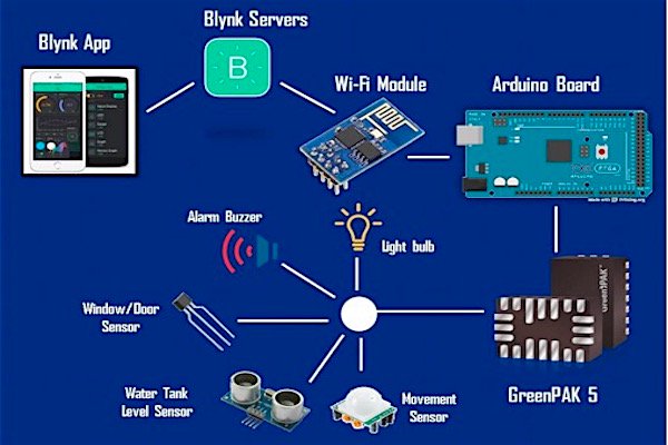
As shown in the following Figure, the smart home structure works as a bi-directional network. It can be explained with two simple general examples:
Controlling output components:
If the user wishes to turn ON a light bulb located inside the home, they simply have to press the button widget associated with the light bulb. After the request is generated, the Boolean data (LOW or HIGH) travels to the Blynk servers, which tell Arduino to turn the bulb ON. The Arduino then processes the data and begins the I2C transmission to the Silego GreenPAK (SLG46538V in this case, but it can work similarly with SLG46537V, SLG46533V and other common GreenPAKs with Asynchronous State Machine (ASM)). The value of the register 0xF4 is changed to 0x01, which turns the first bit of the register I2C block virtual output to HIGH. This is associated at the same time with pin 7 (light bulb) in GP design which forces that digital output pin to HIGH, energizing the relay through a circuit created. When the button in the button widget of the app is un-pressed, the output is turned OFF.
Monitoring input sensors:
Let’s suppose at night when everybody is sleeping, an intruder decides to enter the house through a window. As soon as they try to open the window, an alarm and specific lights will be turned ON (it was set that way in GP Design). The Arduino will be frequently monitoring all the GP5’s connected sensors through I2C (reading the register 0xF0), so it will detect a change in the register value. As in our scenario, the value will be 0x08, which will mean that the digital input pin 4 is active, which will eventually turn a widget LED ON and send a notification to the app, prompting the user for security. [READ MORE]
Comments :